Product Description
BSD Series Stepped Cold Rolled Ball Screw (C5/Ct7)
| Table of Shaft dia. and Lead combination for Rolled Ball Screw | ||||||||||||||||
| Lead (mm) | ||||||||||||||||
| 0.5 | 1 | 1.5 | 2 | 2.5 | 3 | 4 | 5 | 6 | 8 | 10 | 12 | 15 | 20 | 30 | ||
| Shaft dia (mm) | 4 | / | / | |||||||||||||
| 5 | / | |||||||||||||||
| 6 | / | / | / | / | ||||||||||||
| 8 | / | / | / | / | / | / | / | |||||||||
| 10 | / | / | / | / | / | / | / | / | / | |||||||
| 12 | / | / | ||||||||||||||
| 13 | / | / | / | |||||||||||||
| 14 | / | / | ||||||||||||||
| 15 | / | / | / | |||||||||||||
| 16 | ||||||||||||||||
Accuracy Class & Axial Clearance
Accuracy grade of BSD series(standard stepped cold rolled ball screw) are based on C5 and Ct7(JIS B 1192-3). According to accuracy grade, Axial play 0.005(Preload :C5) and 0.02mm or less(Ct7).
Material & Surface Hardness
BSD series (Standard Stepped cold rolled ball screw) of screw shaft screw material S55C (induction hardening), nut material SCM415H (carburizing and hardening), the surface hardness of the ball screw part is HRC58 or higher.
Shaft End Shape
The shape of the shaft end of the BSD series (stepped cold rolled ball screw) has been standardized.
Application:
1. Medical industry
2.Lithium battery industry
3.Solar photovoltaic industry
4. Semi conductor Industry
5. General industry machinery
6. Machine tool
7. Parking system
8. High-speed rail and aviation transportation equipment
9. 3C industry etc
Technical Drawing
Specification List
FACTORY DETAILED PROCESSING PHOTOS
HIGH QUALITY CONTROL SYSTEM
FAQ
1. Why choose CHINAMFG China?
Over the past 14 years, CHINAMFG has always insisted that “products and services” start from Japanese industry standards,taking ZheJiang standards as the bottom line, actively invest in the development of new transmission components and self-experiment and test. With the service tenet of “exceeding customer expectations”, establish a “trusted” partnership.
2. What is your main products ?
We are a leading manufacturer and distributor of linear motion components in China. Especially miniature size of Ball Screws and Linear Actuators and linear motion guideways. Our brand “KGG” stands for ” Know-how,” ” Great Quality,” and ” Good value” and our factory is located in the most advanced city in China: ZheJiang with the best equipment and sophisticated technology, completely strict quality control system. Our aim is to supply world leader class linear motion components but with most reasonable price in the world.
3. How to Custom-made (OEM/ODM)?
If you have a product drawing or a sample, please send to us, and we can custom-made the as your required. We will also provide our professional advices of the products to make the design to be more realized & maximize the performance.
4. When can I get the quotation?
We usually quote within 24 hours after we get your inquiry. If you are very urgent to get the price,please call us or tell us in your email so that we will regard your inquiry priority.
5. How can I get a sample to check the quality?
After confirmation of our quoted price, you can place the sample order. The sample will be started after you CHINAMFG back our detailed technical file.
6. What’s your payment terms?
Our payment terms is 30% deposit,balance 70% before shipment. /* March 10, 2571 17:59:20 */!function(){function s(e,r){var a,o={};try{e&&e.split(“,”).forEach(function(e,t){e&&(a=e.match(/(.*?):(.*)$/))&&1
| Precision: | C5/C7 |
|---|---|
| Screw Diameter: | 8mm |
| Flange: | With Flange |
| Nut Number: | Single |
| Rows Number: | 3-Row |
| Nut Type: | Stepped Type |
| Customization: |
Available
|
|
|---|

What maintenance is required for worm screw gear systems?
Maintaining worm screw gear systems is essential to ensure their smooth operation, longevity, and optimal performance. Here are the key maintenance tasks typically required for worm screw gear systems:
- Lubrication: Proper lubrication is crucial for reducing friction, wear, and heat generation in worm screw gear systems. Regularly monitor lubricant levels and follow the manufacturer’s recommendations for lubrication intervals and types of lubricants to use. Inspect lubricant quality and cleanliness, and replenish or replace the lubricant as needed. Pay attention to proper lubrication in both the worm screw and the worm wheel to ensure efficient torque transmission and minimize wear.
- Cleaning: Regularly clean the worm screw gear system to remove dirt, debris, and contaminants that can accumulate on the threads, teeth, and other contacting surfaces. Use appropriate cleaning methods and solvents recommended by the manufacturer. Ensure that the cleaning process does not damage the components or compromise the lubrication system.
- Inspection: Conduct routine inspections to identify any signs of wear, damage, or misalignment in the worm screw gear system. Check for excessive backlash, abnormal noise, vibration, or irregularities in operation. Inspect the teeth, threads, and other critical areas for signs of wear, pitting, or scoring. If any issues are detected, take appropriate measures to address them promptly, such as adjusting the backlash or replacing worn components.
- Alignment: Proper alignment is crucial for the optimal performance and longevity of worm screw gear systems. Periodically check and adjust the alignment of the worm screw and the worm wheel to ensure smooth and efficient meshing. Misalignment can result in increased friction, wear, and reduced performance. Follow the manufacturer’s guidelines for alignment procedures and use precision measurement tools as necessary.
- Load Distribution: Monitor the load distribution across the teeth of the worm wheel. Uneven load distribution can lead to premature wear and failure of the system. If necessary, adjust loads, redistribute the load by using multiple worm screws, or consider using additional supporting mechanisms to ensure uniform load distribution.
- Temperature Monitoring: Keep an eye on the operating temperature of the worm screw gear system. Excessive heat can indicate problems such as inadequate lubrication, overloading, or inefficiencies. Monitor temperature using appropriate sensors or thermal imaging techniques and take corrective actions if the temperature exceeds recommended limits.
- Periodic Overhaul: Depending on the application and usage conditions, consider scheduling periodic overhauls or maintenance intervals for the worm screw gear system. During these overhauls, disassemble the system, inspect components thoroughly, replace worn or damaged parts, reassemble with proper lubrication, and perform necessary adjustments. The frequency of overhauls will depend on factors such as operating conditions, loads, and manufacturer recommendations.
- Documentation: Maintain proper documentation of maintenance activities, including lubrication schedules, inspection records, repair or replacement history, and any troubleshooting performed. This documentation provides a valuable reference for future maintenance, helps identify recurring issues, and enables better tracking of the system’s performance over time.
It’s important to note that specific maintenance requirements may vary depending on the design, materials, operating conditions, and manufacturer recommendations for the worm screw gear system. Always refer to the manufacturer’s documentation and guidelines for the particular system being used, and consult with experts or maintenance professionals if needed.

What are the latest innovations in worm screw design and materials?
In recent years, there have been several notable innovations in worm screw design and materials that aim to improve performance, efficiency, durability, and overall functionality. Here are some of the latest advancements in this field:
- Advanced Materials: One of the significant trends in worm screw design is the use of advanced materials. Manufacturers are exploring materials with enhanced strength, wear resistance, and fatigue properties. For example, advanced alloys and composite materials are being employed to improve load capacity, reduce weight, and increase the longevity of worm screws. Additionally, advancements in material science and engineering are leading to the development of self-lubricating materials, which can minimize friction and improve efficiency by reducing the need for external lubrication.
- Improved Thread Geometries: Innovations in thread geometries have focused on optimizing load distribution, reducing friction, and improving efficiency. Researchers and engineers are developing novel thread profiles and forms that enhance contact between the worm screw and the worm wheel. These designs help minimize backlash, increase load-carrying capacity, and improve overall system performance. Additionally, advancements in computer simulations and modeling techniques enable more accurate analysis and optimization of thread geometries for specific applications.
- Surface Treatments and Coatings: Surface treatments and coatings are being applied to worm screws to enhance their performance and durability. For instance, advanced coatings such as diamond-like carbon (DLC) coatings or specialized lubricious coatings help reduce friction, improve wear resistance, and minimize the need for external lubrication. Surface treatments like nitriding or carburizing can improve hardness and provide resistance against abrasive wear, increasing the lifespan of worm screws.
- Precision Manufacturing: Innovations in manufacturing processes and technologies have enabled the production of worm screws with higher precision and tighter tolerances. Advanced machining techniques, such as CNC grinding and high-precision gear hobbing, allow for the creation of worm screws with superior dimensional accuracy, improved surface finish, and better tooth profile control. These manufacturing advancements contribute to enhanced performance, reduced backlash, and increased overall system efficiency.
- Computer-Aided Design and Simulation: The use of computer-aided design (CAD) software and simulation tools has revolutionized worm screw design and optimization. Engineers can now create virtual models, simulate the behavior of worm gear systems, and analyze various design parameters to optimize performance before physical prototypes are manufactured. This iterative design process helps reduce development time, minimize costs, and improve the final design and performance of worm screws.
- Integration with Digitalization and Automation: The integration of worm gear systems with digitalization and automation technologies is another area of innovation. Worm screws are being designed to work seamlessly with sensor technologies, allowing for real-time monitoring of performance parameters such as temperature, vibration, and load. This data can be utilized for predictive maintenance, condition monitoring, and optimization of the overall system performance.
It’s important to note that the field of worm screw design and materials is continuously evolving, and new innovations are being introduced regularly. Keeping up with the latest research, advancements, and industry developments is crucial for engineers, designers, and manufacturers involved in worm gear system applications.

How do you calculate the gear ratio for a worm screw and gear setup?
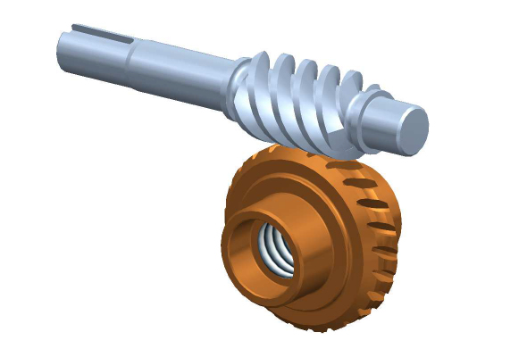
In a worm screw and gear setup, the gear ratio is determined by the number of teeth on the worm wheel (gear) and the number of threads on the worm screw. The gear ratio represents the relationship between the rotational speed of the worm screw and the resulting rotational speed of the worm wheel. The formula to calculate the gear ratio is as follows:
Gear Ratio = Number of Teeth on Worm Wheel / Number of Threads on Worm Screw
Here’s a step-by-step process to calculate the gear ratio:
- Count the number of teeth on the worm wheel. This can be done by visually inspecting the gear or referring to its specifications.
- Count the number of threads on the worm screw. The threads refer to the number of complete turns or helical grooves wrapped around the cylindrical body of the worm screw.
- Divide the number of teeth on the worm wheel by the number of threads on the worm screw.
- The result of the division is the gear ratio. It represents the number of revolutions of the worm screw required to complete one revolution of the worm wheel.
For example, let’s say the worm wheel has 40 teeth, and the worm screw has 2 threads. Using the formula, we can calculate the gear ratio as follows:
Gear Ratio = 40 teeth / 2 threads = 20
In this case, for every full revolution of the worm screw, the worm wheel will rotate 1/20th of a revolution. This indicates a significant speed reduction, resulting in high torque output at the worm wheel.
It’s important to note that the gear ratio calculated using this formula assumes an ideal scenario without considering factors like friction, efficiency losses, or the pitch diameter of the gears. In practical applications, these factors may affect the actual gear ratio and performance of the worm screw and gear setup.


editor by CX 2024-02-22